2009-11-21

mingl - depth sorting order

Depth sorting is a traditional fix for a variety of problems;

However, it is a unsolvable problem. Consider that you have two long triangles, and you point the camera down the longest side of each. The triangles overlap; So if you draw one before the other, one triangle will depth clip the other, resulting in incorrect blending. The traditional fix is to draw with depth writing disabled, and then draw with color writing disabled. This can fix that special case, but causes other problems like highlights and odd depth clippings.

As a direct result, you generally need to draw all opaque objects first; Then perform the above method, which should correctly render the transparent polygons. however, as it may be obvious, you need a specialized structure to deal with being able to partition and sort your meshes by transparency.

This problem is not related to alpha clipping or depth fragment alpha, which is the problem of a semitransparent object occluding other geometry. In practice, it does well to solve this issue though.

Here is the difference between depth sorting and non depth sorting your objects; Notice there are still some errors, but the effect is minimal:


This effect is largely a matter of taste; And mingl is not responsible for how you draw, only for abstracting the graphics rendering hardware.

In a unrelated event; Any of you that know the Atari 2600 game "Adventure"? Well, you had better know about this hilarity: Adventure 2600 Reboot

Sound familiar? 

Yeah. But it's not like my version; and after playing  their version, I think I can one up this, so I'll try and make a "Adventure Remix" using my mingl / xcore system. The benefits, are it is something I like to make, as well as something people can probably enjoy messing with for a little bit. I'm just drawing and modeling, but I do not plan to clone or copy the game, instead I want to recreate the spirit of the game, and add my own little improvements. Plus, with my new toon hemi shader, it can look all sorts of shiny.

Til' later;

-Z

2009-11-17

mingl - progress updates

xcore / mingl is moving along quite well.

Operating on a basic create / destroy paradigm, with bind/unbind as the activation mechanism and load as the data send mechanism, it works well for abstracting graphics hardware and allowing for faster creation of intense graphics applications.

Here's a nonsense screenshot:


This is a vector field represented as moving transparent spheres that are depth sorted. The vector field is generated by 3 functions modulated together.

The shading is generated via vertex and fragment program. The meshes are using a VBO/IBO abstraction paradigm.

All is well. More later.

2009-11-06

DXT Texture compression

DXT image compression (also S3TC) allows you to save:

DXT1_RGB -> 1:8  RGB 565 4 level only
DXT1_RGBA -> 1:8  RGB 565 4 level and 1 bit alpha channel
DXT5_RGBA -> 1:4  RGB 565 4 level and 7 level alpha channel

As a result, for certain textures DXT can be used to compress images with reasonable loss of clarity.


Most importantly, within the DXT5 compression scheme, you still have 4x4 texel blocks interpolating between two color values. These color values are RGB565 (5 bits of red, 6 bits of gree, 5 bits of blue) and thus the green channel can be more precise. Also, the alpha channel has all 8 bits, but interpolates between 7 alpha values per texel. As a result, you can use DXT5 to store compressed normal maps by storing the x component in the green channel, and the y value in the alpha component. Then, in the shader, you can calculate the missing z value from assuming your normal map was actually normalized (x^2 + y^2 + z^2 = 1).

More updates later.
Z out.

2009-11-05

Cube Sphere

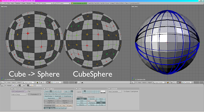
The Naiive implementation of making a Cube a Sphere is to make a cube, then select all verticies and "Mesh -> Transform -> To Sphere". This results in severe distortion along the principal axes, and a poor approximation of a sphere, as a result.

A more correct implementation is to notice that this is analogous to taking two planes centered at the origin, and rotating them n time in discrete angular intervals, thus chopping space into uniform areas, resulting in far less distortion.

Neither approach is perfect because you cannot comb a hairy sphere smooth. But the Cube Sphere is far superior, and easier to generate using a difference equation.


Cube Spheres are good for working with planets and large scale data, but don't have many other uses besides easier texturing of spheres.

..I can;t seem to figure out how to post data to blogger... how to post a .py script?

It's not 100% perfect; copy paste into notepad or something

Here goes nothin':

#!BPY
"""
Name: 'CubeSphere'
Blender: 249
Group: 'AddMesh'
Tooltip: 'Creates a Cube Map sphere'
"""
__author__ = "Izcalli64"
__url__ = ("blender", "http://imaginaryz.blogspot.com");
__version__ = "0.0 2009-11-05"

import Blender
import math;

def generate_grid( ndiv, spanning ):

    #
    #Optimal spanning value: Unknown
    #Optimal spanning equation: Unknown
    #

    radius = 1.0;    #Fixed; don't vary this.
    points = [];
    ndiv = int( ndiv );
   
    #From experiment; It looks like you need a transformation from radial space to manhatten space:
    #
    #the only fixed points are the 4 corner points, from which there are lateral and vertical lines;
    #These lines must have points distributed on them evenly, by angle.
    #These lines are NOT consistent, but do consist of great circle arcs.
    #
    #SOLUTION:
    #
    #Generate a cube sphere by taking 2 lists of evenly distributed angles;
    #Generate the great circle planes (planes) that intersect the angles;
    #Calculate all points on the grid that are the intersections of both:
    #    The sphere of radius R
    #    Great circles A and B (will always form a line, no matter what.
    #The result:
    #    Quite a substantial amount less error than the other method. (see .blend)
    #The problem:
    #    Hard to optimize
    #
    dtr = math.pi/180.0;
    mina = 45.0 * dtr;    #Minimum angle (45 = pi/4)
    maxa = 135.0 * dtr;    #Maximum angle (135 = 3*pi/4)
    rangea = maxa - mina;
    dela = (maxa - mina)/float(ndiv-1);
    spanrange = dela * spanning;

    #Generate strip angles (for consistency)
    stripa = [];
   
    stripa.append( [ mina, math.sin(mina), math.cos(mina) ] );
    idex = 1;
    ia = mina + dela;
    while( idex < (ndiv-1) ):

        #Default angles (angular evenness)
        #stripa.append( [ ia, math.sin(ia), math.cos(ia) ] );

        #Corrected angles:
        delv = 2.0 * ((float(idex)/float(ndiv-1)) - 0.5);    #-1.0..1.0 range
        dels = 0;
        if( delv < 0 ):
            dels = -1.0;
        elif( delv > 0 ):
            dels = 1.0;       
           
        #Correction quadratic equation (B-spline could be more effective)
        #ian = dels * (delv*delv) * spanrange + ia;
        #ian = -dels * (1.0 - (delv*delv)) * spanrange + ia;
        ian = -dels * (1.0 - abs(delv)) * spanrange + ia;#Very simple; linear. Problem is not linear.


        #print delv, dels, -dels * (1.0 - (delv*delv));
       
        stripa.append( [ ian, math.sin(ian), math.cos(ian) ] );

        ia += dela;
        idex += 1;
    stripa.append( [ maxa, math.sin(maxa), math.cos(maxa) ] );
   
    for ex in stripa:
        print ex;
   
    #Generate strips:
    iy = 0;
    while( iy < ndiv ):
        ix = 0;
        while( ix < ndiv ):
       
            #Plane X / Circle X
            PXx = stripa[ix][2];    #cos(x)
            PXy = stripa[ix][1];    #sin(x)
            PXz = 0;
           
            #Plane Y / Circle Y
            PYx = stripa[iy][2];    #cos(y)
            PYy = 0;
            PYz = stripa[iy][1];    #sin(y)
           
            #Cross product (direction vector to use; can be optimized:)
            #nx = PXy * PYz - PXz * PYy;
            #ny = PXz * PYx - PXx * PYz;
            #nz = PXx * PYy - PXy * PYx;
            nx =   PXy * PYz;
            ny = - PXx * PYz;    #Optimized cross product from zero factors
            nz = - PXy * PYx;
           
            #Normalize direction vector
            nm = math.sqrt( nx*nx + ny*ny + nz*nz );
            nx /= nm;
            ny /= nm;
            nz /= nm;

            #Apply scaling of shape
            tx = radius * nx;
            ty = radius * ny;
            tz = radius * nz;

            points.append( [tx,ty,tz] );
           
            ix += 1;
        iy += 1;
       
    return points;
   
def generate_points_swizzle( points, comp0, comp1, comp2, neg0, neg1, neg2 ):

    newpoints = [];
   
    sw0 = comp0;
    sw1 = comp1;
    sw2 = comp2;
   
    for P in points:
   
        np = [0,0,0];#[ P[sw0], P[sw1], P[sw2] ];
        if( neg0 != 0 ):
            np[0] = -P[sw0];
        else:
            np[0] = P[sw0];
           
        if( neg1 != 0 ):
            np[1] = -P[sw1];
        else:
            np[1] = P[sw1];
           
        if( neg2 != 0 ):
            np[2] = -P[sw2];
        else:
            np[2] = P[sw2];
        newpoints.append( np );
       
    return newpoints;
   
def generate_grid_uv( xdiv, ydiv ):

    uvs = [];
    iy = 0;
    while( iy < (ydiv) ):
        ix = 0;
        while( ix < (xdiv) ):

            u0 = float( ix ) / float(xdiv-1);
            v0 = float( iy ) / float(ydiv-1);
           
            uvs.append( [u0,v0] );

            ix += 1;
        iy += 1;
       
    return uvs;

def generate_grid_facelist( xdiv, ydiv, offset_index ):

    faces = [];

    iy = 0;
    while( iy < (ydiv-1) ):
        ix = 0;
        while( ix < (xdiv-1) ):

            fxy00 = int(offset_index + ix + (iy * xdiv));
            fxy10 = int(offset_index + ix + 1 + (iy * xdiv));
            fxy01 = int(offset_index + ix + ((iy + 1) * xdiv));
            fxy11 = int(offset_index + ix + 1 + ((iy + 1) * xdiv));
       
            faces.append( [fxy00,fxy10,fxy11,fxy01] );

            ix += 1;
        iy += 1;
       
    return faces;

def generate_cubesphere( in_radius, in_divisions, in_evenness ):

    #Generate each cube face, simply rotate it's data to match what we want.
    ndiv = in_divisions + 2;
   
    faces = [];
    points = [];
    uvs = [];
    origpoints = generate_grid( ndiv, in_evenness );#x,y,z
   
    faces.extend( generate_grid_facelist( ndiv, ndiv, 0 ) );
    points.extend( origpoints );
    uvs.extend( generate_grid_uv( ndiv, ndiv ) );

    faces.extend( generate_grid_facelist( ndiv, ndiv, len(points) ) );
    points.extend( generate_points_swizzle( origpoints, 2,1,0, 0,0,0 ) );    #x,y,z => z,y,x
    uvs.extend( generate_grid_uv( ndiv, ndiv ) );
   
    faces.extend( generate_grid_facelist( ndiv, ndiv, len(points) ) );
    points.extend( generate_points_swizzle( origpoints, 2,0,1, 0,0,0 ) );    #x,y,z => x,z,y
    uvs.extend( generate_grid_uv( ndiv, ndiv ) );

    faces.extend( generate_grid_facelist( ndiv, ndiv, len(points) ) );
    points.extend( generate_points_swizzle( origpoints, 0,1,2, 1,1,1 ) );    #x,y,z => -x,-y,-z
    uvs.extend( generate_grid_uv( ndiv, ndiv ) );
   
    faces.extend( generate_grid_facelist( ndiv, ndiv, len(points) ) );
    points.extend( generate_points_swizzle( origpoints, 2,1,0, 1,1,1 ) );    #x,y,z => -z,-y,-x
    uvs.extend( generate_grid_uv( ndiv, ndiv ) );
   
    faces.extend( generate_grid_facelist( ndiv, ndiv, len(points) ) );
    points.extend( generate_points_swizzle( origpoints, 2,0,1, 1,1,1 ) );    #x,y,z => -x,-z,-y
    uvs.extend( generate_grid_uv( ndiv, ndiv ) );
   
    #Scale all points by radius value (lol?)

    return points,uvs,faces;
   
def main():
    Draw = Blender.Draw
    PREF_RADIUS = Draw.Create(1.0)        #"Radius" of cube-sphere
    PREF_DIVISIONS = Draw.Create(7)    #Divisions per face
    PREF_EVENNESS = Draw.Create(0.0)    #Evenness of point distribution (by area weighting, so uv texture distortion is absolute minimal at default value)

    if not Draw.PupBlock('Add CubeSphere', [\
    ('Radius:', PREF_RADIUS,  0.01, 100.0, 'Radius for the main ring of the torus'),\
    ('Divisions:', PREF_DIVISIONS,  0, 256, 'Number of subdivisions to generate'),\
    ('Evenness:', PREF_EVENNESS,  -1.0, 1.0, 'Evenness scaling for evaluation'),\
    ]):
        return;
       
    verts, uvs, faces = generate_cubesphere( PREF_RADIUS.val, PREF_DIVISIONS.val, PREF_EVENNESS.val );
   
    #Every vertex has an exact and corresponding uv value to it (sticky uv)
    #As a result, it shall be simple to assign face UV's.

    meshobj = Blender.Object.New( 'Mesh', 'CubeSphere' );
    meshdata = Blender.Mesh.New();
   
    meshdata.verts.extend(verts);
    meshdata.faces.extend(faces);
   
    #Apply uv coordinates:
    meshdata.addUVLayer("CubeMap");
    meshdata.activeUVLayer = "CubeMap";

    if( meshdata.faceUV ):
        for f in meshdata.faces:
       
            vinds = [];
            for v in f.verts:
                vinds.append( v.index );
               
            vdin = 0;
            for vdex in f.uv:
                uvd = uvs[ vinds[ vdin ] ];
                vdex[0] = uvd[0];
                vdex[1] = uvd[1];
                vdin += 1;
       
    else:
        print "#ERROR; Face UV could not be enabled??";
   
    meshdata.calcNormals();
    meshdata.update();
   
    meshobj.link( meshdata );
    Blender.Scene.GetCurrent().objects.link( meshobj );    #Is this deprecated? #ERROR
   
main();
#Blender.Draw.PupMenu("Error%t|This script requires a full python installation")